Controlling Raspberry-Pi LEDs the Hard Way
Yesterday I finally got my hands on a multimeter and could read out resistor values. As a colourblind person, I was unaware that this would bite me.
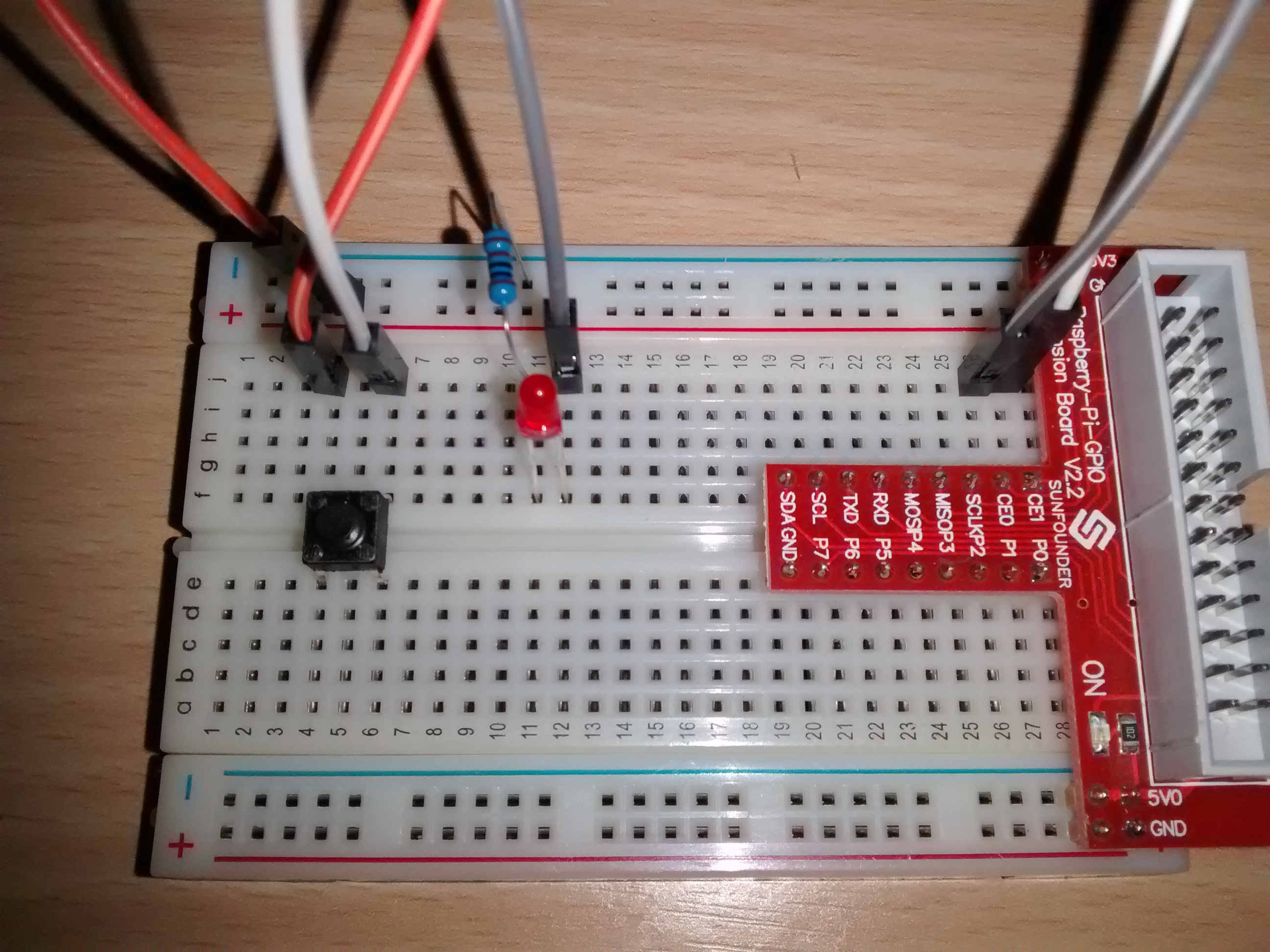
I decided to go ahead and play around with a simple schematic. The goal: Make the LED light up as long as the button is pressed.
I decided to do all with a multiprocessed Python application. You know... for funsies. But also because I am more of a software than a hardware guy.
To access the GPIOs, I'm using the excellent pigpio library.
The Challenge
Write a Python application which uses multiple processes to react to external stimuli.
Starting Point
- Button connected to GPIO 7 (CE1 on the Ext. Board).
- LED connected to GPIO 8 (CE0 on the Ext. Board).
Plan of Action
- Write three sub-processes (in addition to the main process):
- One process, the "Button Monitor", which reacts to button presses by converting them into "Button State Change Events".
- One process, the "LED Controller", which reacts to "LED State Change" events by converting them to GPIO signals.
- One "Event Dispatch Process". This one combines all message queues and knows which events should be sent to which process.
Material Used
- SunFounder Raspberry-Pi-GPIO Extension Board V2.2
- 1 kΏ Resistor
- 1 LED
- 1 Button
- 3 Jumper Wires
- 1 Bread Board
Wiring
I don't have anything to draw schematics yet... so a crappy potato photo will have to do:

Code
Now this is the amusing part. And too big to post here. The resulting code can be found in my GitHub repository.
Conclusion
It works. And the code of the individual processes is fairly simple.
But...
- I have two processes wach having a connection to the pigpiod daemon. It irks me. I'd prefer having only one connection. But it's good enough for now.
- It's not possible to attach event-handlers. The handling is completely hard-coded in the dispatcher process. Again, good enough for a quick-and-dirty script.
